Follow here the story of the rig DIAMONDS (Detection of Ignition and Adaptive Mitigation Onboard for Non-Damaged Spacecrafts) for parabolic flights funded by the French Space Agency (CNES).
The UPMC rig flew for the first time on October, 7th - 9th 2014. Click on the picture below to see the flying team.

See here for more specific details about this parabolic flight campaign or read the full story of the UPMC rig below.
Step 1 November 2012 - October 2013
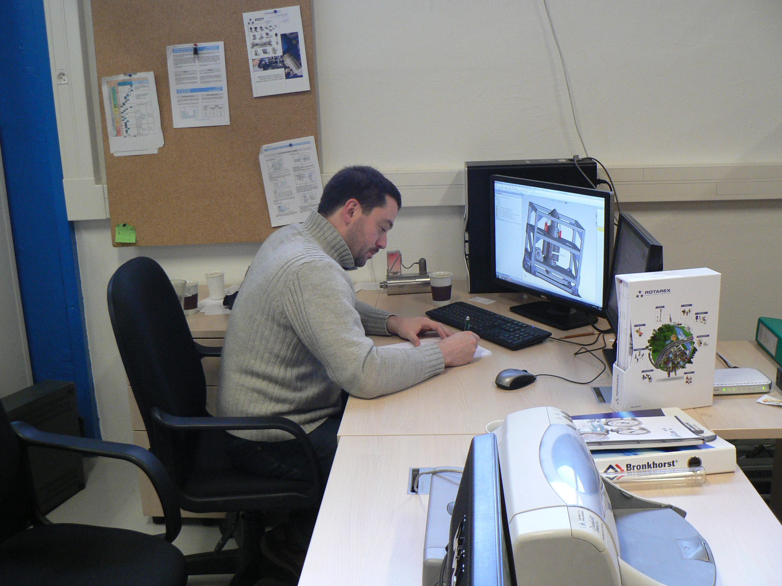
In close collaboration with Brian Verthier (Novespace), Jean-Marie Citerne is designing the new rig at the lab. This procedure namely incorporates structural computations to comply with the safety constraints onboard the zeroG airplane.
Board with the experiment here.
Have a look at the brand new combustion chamber here.
Step 2 November 2013
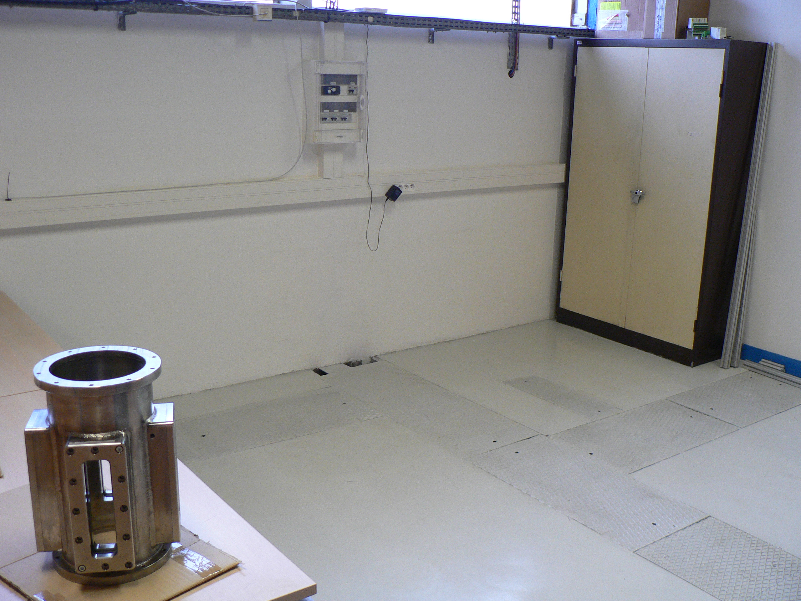
We received the combustion chamber (see in the lower left corner) especially designed for the parabolic flights.
Step 3 December 2013
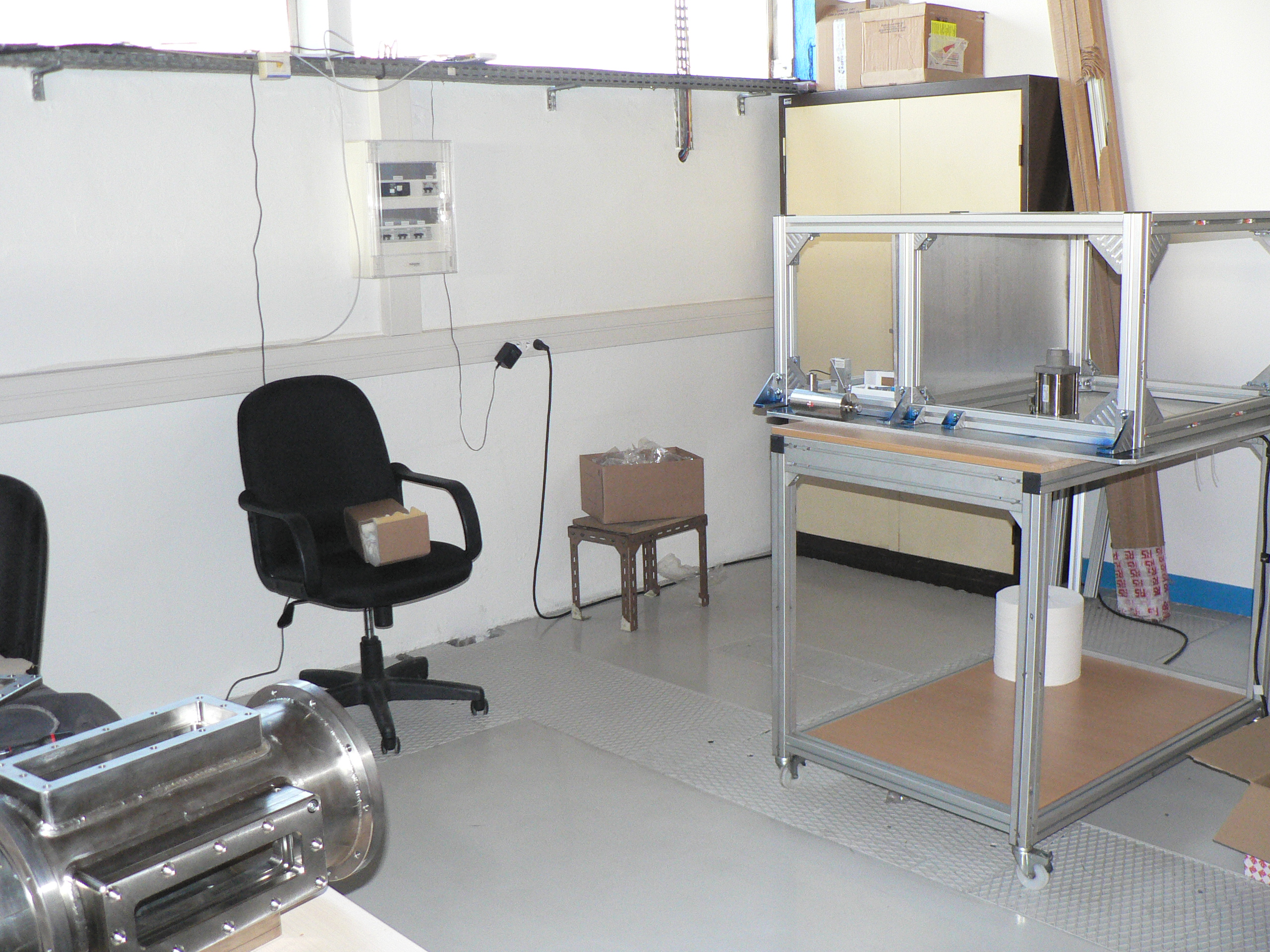
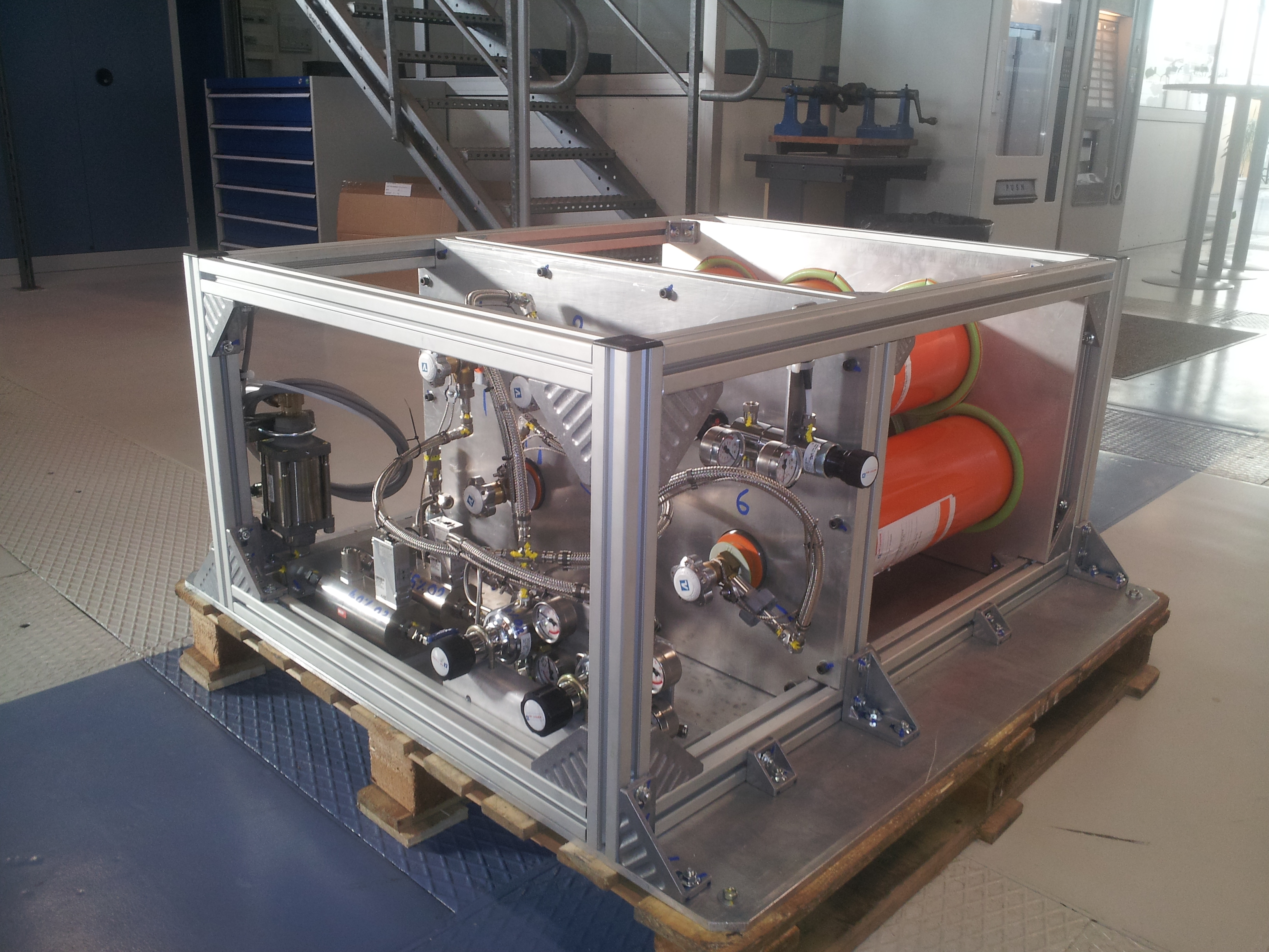
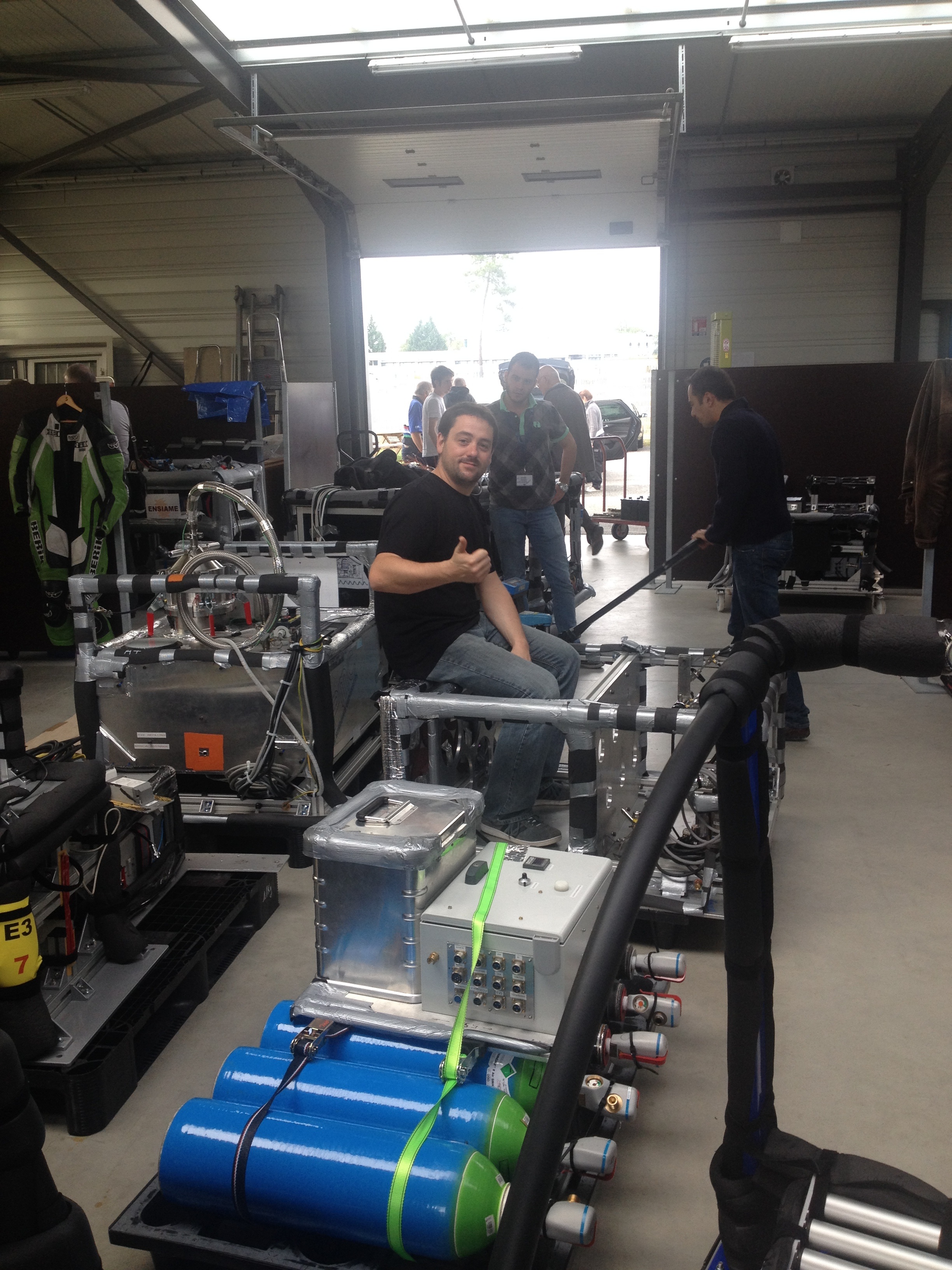
We start mounting the rig. On the table, you can see the rig where the bottles of gases will be inserted. This rig is dedicated to the preparation of the stream that will flow through the combustion chamber.
Look at the movie to see Jean-Marie Citerne and Guillaume Legros mounting the rig, after Jean-Philippe Chauvet has cut the beams: here
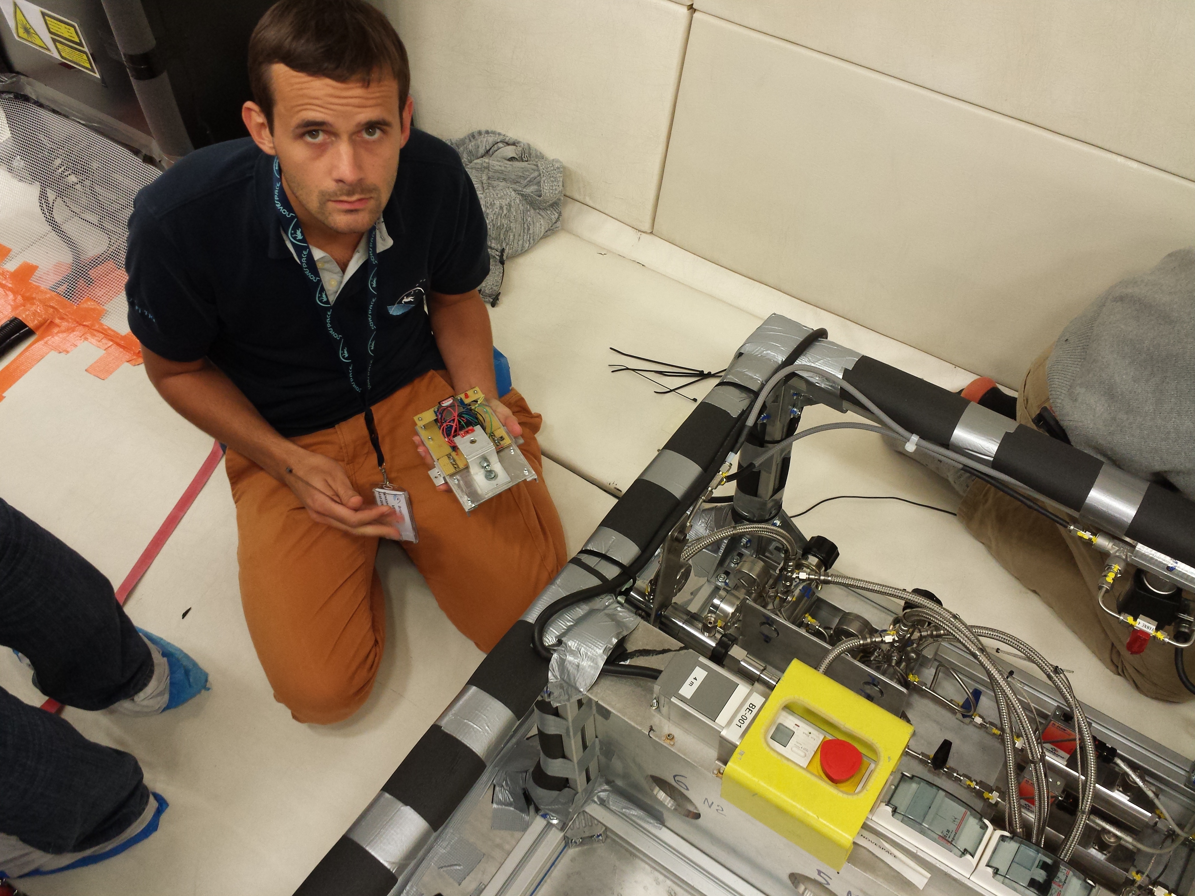
Hugo Dutilleul designed a small wire holder. This will help design the ultimate ignition system that will enable the study of the flame spread over electrical wires in microgravity, in collaboration with Prof. Osamu Fujita (Univ. Hokkaïdo, Japan). Look at the movie of the first ignition experiment here.
Hugo is making the bottles' holder.
Step 4 January 2014
The rack dedicated to the preparation of oxidizer flow is now operational.
After it has been assembled, the combustion chamber is now incorporated into its specific rack. The chamber especially had to be certified for a given working overpressure.

Step 5 February / March 2014
Along the final experiments on ground, a mechanical failure located at the inlet of the combustion chamber happened. We had to cancel our participation to ESA parabolic flight campaign, scheduled in April.
After few days of depression, we designed a tougher solution. Sébastien Rouquette, CNES Parabolic Flight technical coordinator, expertised the solution to evaluate the step that needed to be bridged. He supported financially and technically the improvements.
Step 6 April / May 2014
Incorporation of the new inlet of the combustion chamber. This inlet has been designed to allow disassembling, cleaning, and re-assembling between 2 flights.
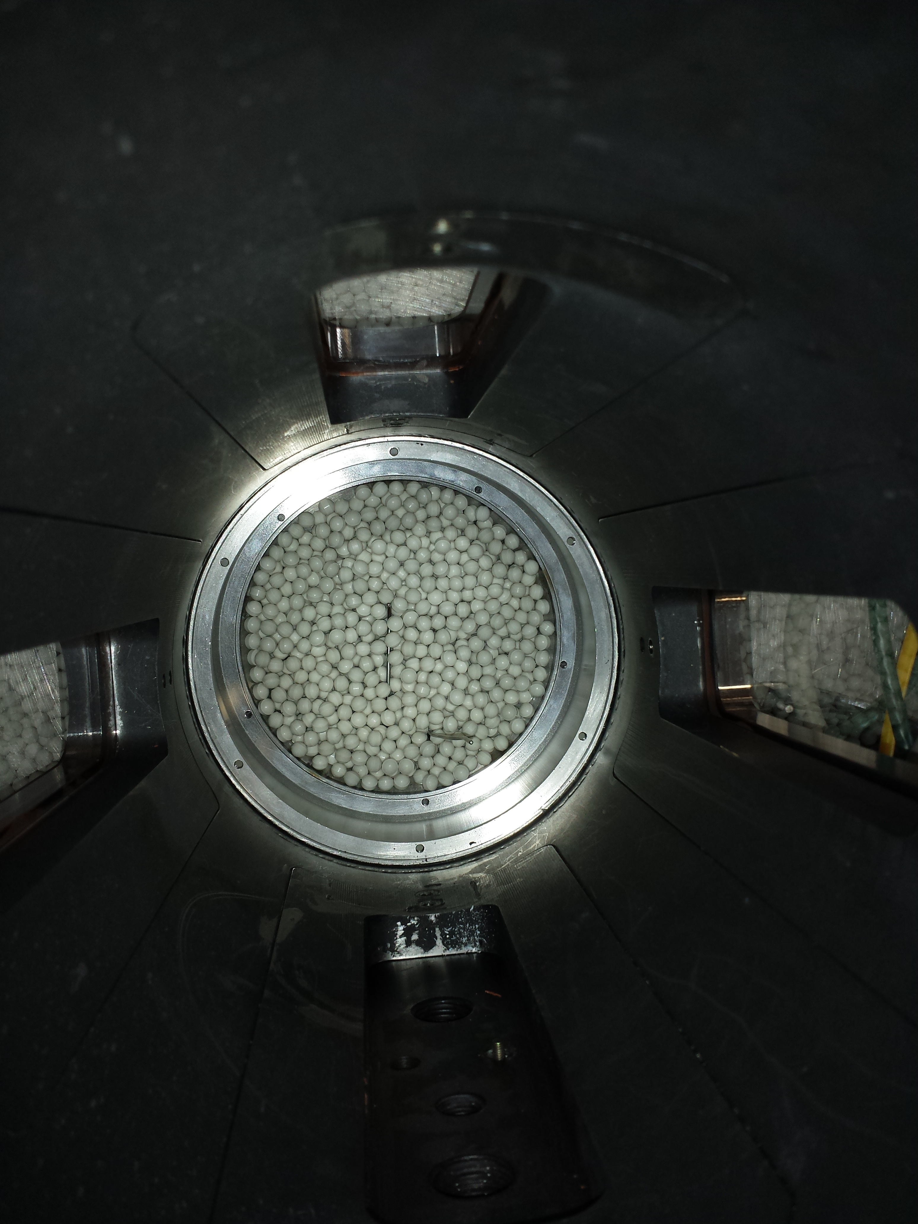
The following pictures captured from the combustion chamber outlet show the different layers that compose the new inlet.
At the inlet of the conical part, a stainless steel grid.

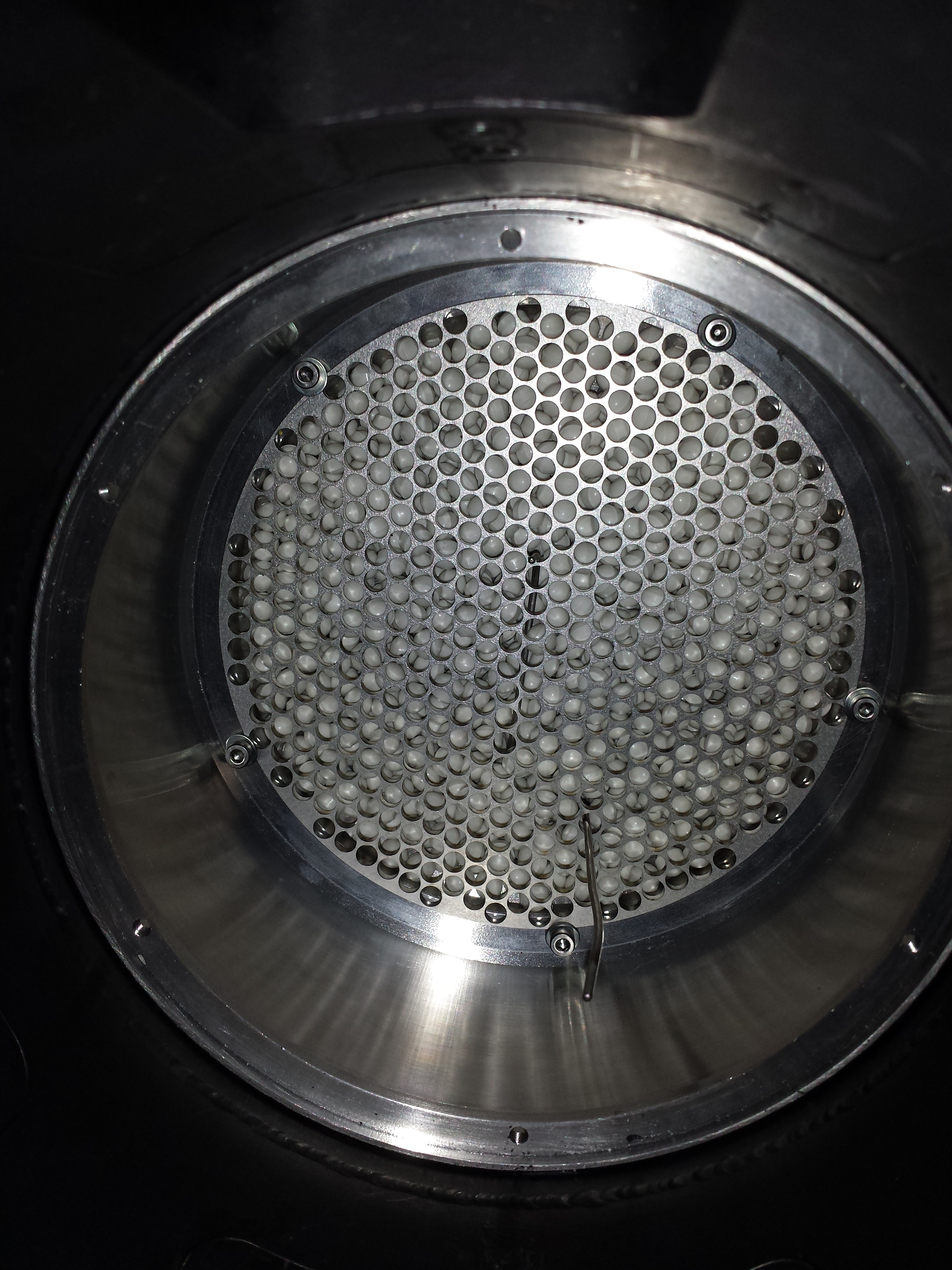
The conical part is then filled with ceramic balls that will make the oxidizer inflow quiescent.
A second stainless steel grid is then screwed to the chamber walls.
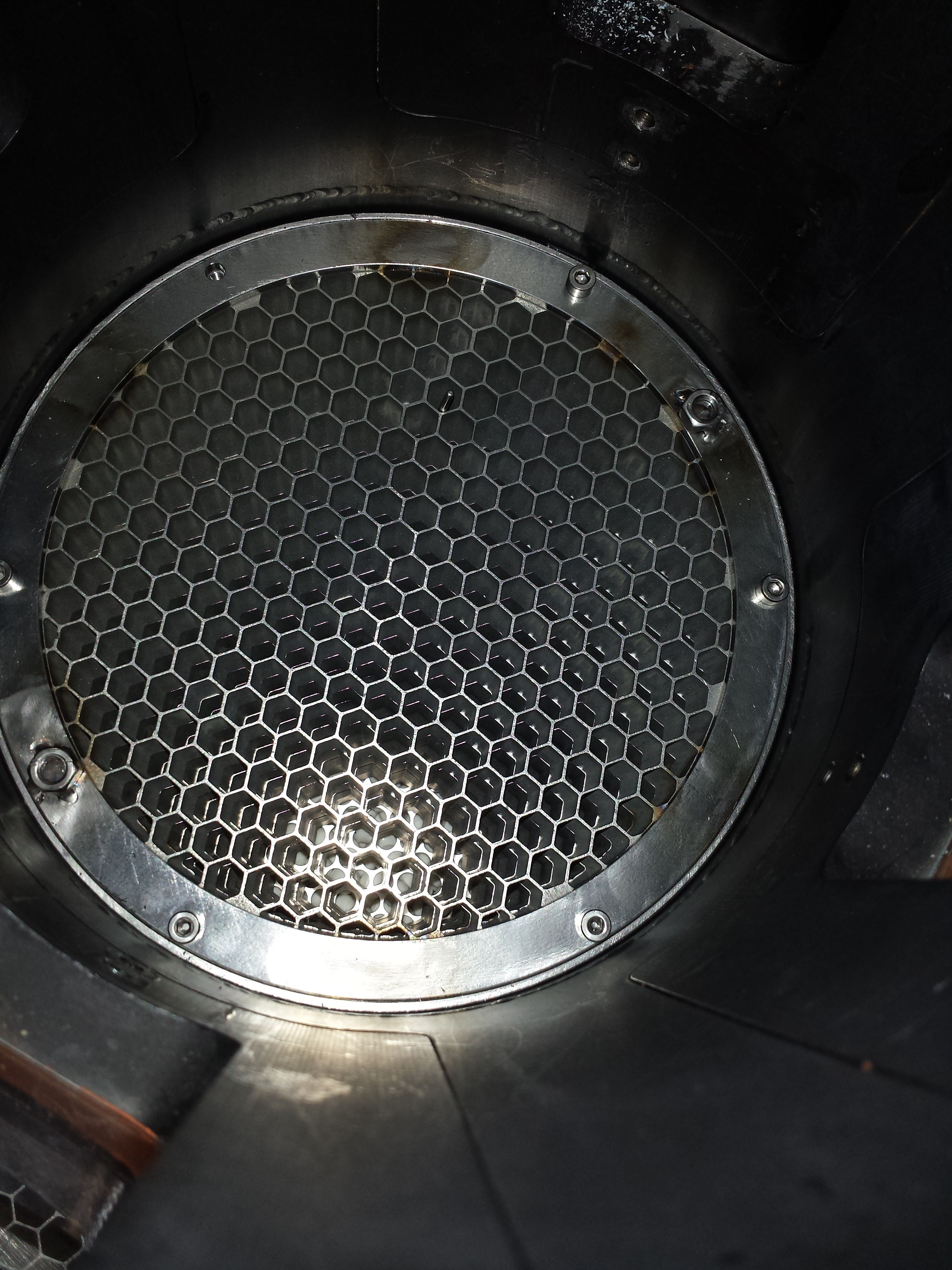
A stainless steel honeycomb will eventually straighten the oxidizer streamlines.
Step 7 June 2014
Design of the sample holder
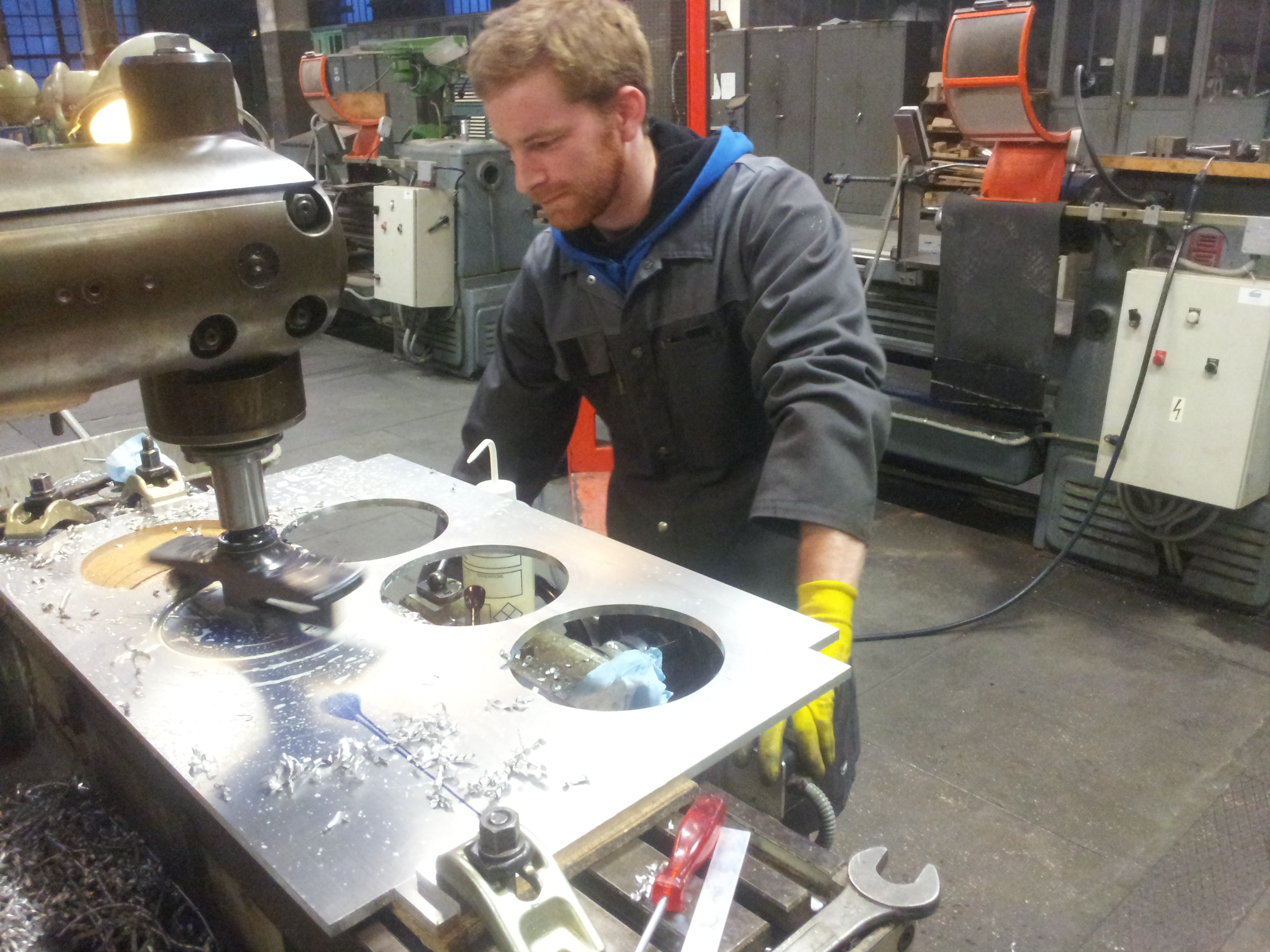
Getting ready for a collaboration with Prof Osamu Fujita (Univ. Hokkaïdo, Japan), we designed a sample holder made of stainless steel and ceramic. Our CNC machine allowed 35 sample holders to be made.
Here is a sample holder that enables the 3 vertical wires to be mounted. Their polyethylene coating will be ignited with the thin horizontal wire wrapped around.

Step 8 July 2014
Validation of the experimental procedures
Assigned by Sébastien Rouquette, Christian Chauveau, Directeur de Recherche at CNRS, headed a committee that validated the rig and its associated operational procedures.
Look at one of the 31 tests conducted to mimic on ground -therefore with buoyancy- 1 flight. We burnt here the coatings of the 3 wires shown above. The air stream flows upwards. The coating is ignited at the top of the coating at the beginning of the movie. On the left, you can see the shadow of the coatings that are consumed. In the middle, you can see the frames provided by another camera capturing the visible flame. Here, the optical diagnostics settings still need to be optimized.
Step 9 September 2014
Getting ready for the coming parabolic flight campaign
Strengthened by all the steps we had to face, we adjusted the diagnostics settings to make sure that the first campaign will deliver preliminary but significant results. Jacques Baillargeat, engineer at CNRS (Poitiers), especially designed an electronic device allowing the cameras to be synchronized.
Sent by Prof Fujita, Koki Kizawa, student in master degree, joined us for a month. At the end of September, the rig is ready to leave to Bordeaux.
Step 10 Septembre / October 2014
CNES VP 112: first parabolic flights campaign for the rig.
This campaign was the very beginning of an expected collaboration between CNES and JAXA that was especially initiated by Bernard Zappoli (CNES).
The experiments were conducted by the international team surrounding the rig aboard the airplane A300 zeroG. From the left to the right: K. Kizawa (Hokkaïdo Univ., Japan), G. Jomaas (DTU, Denmark), G. Legros (UPMC), O. Fujita (Hokkaïdo Univ., Japan), M. Kikuchi (JAXA, Japan), J.-M. Citerne (UPMC), H. Dutilleul (UPMC).
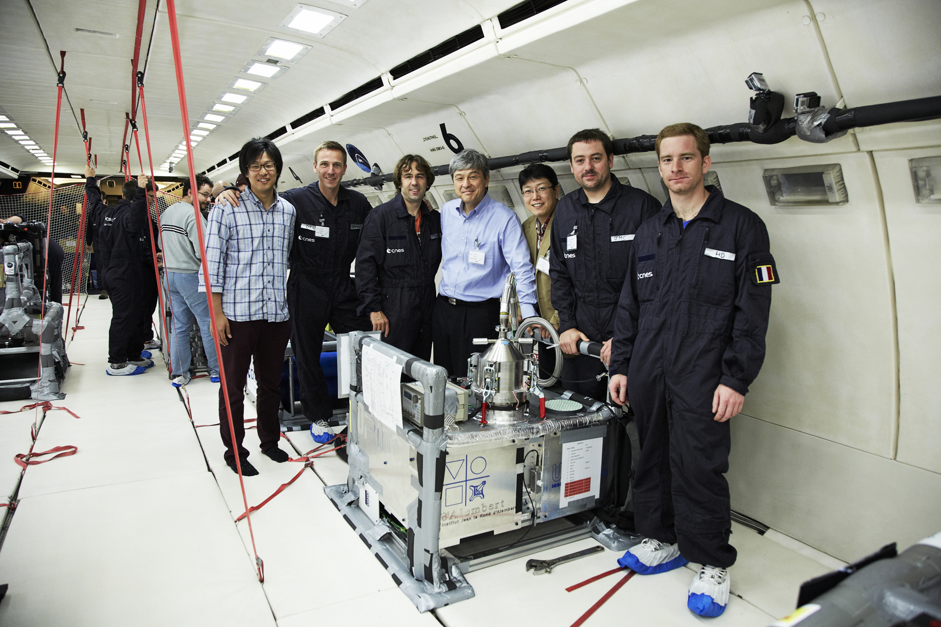
After a final check by Brian Verthier (Novespace), the rig is certified: it will fly.
Now watch the movie by Søren Kristensen, the Danish journalist who recorded the cabin at the time of our first successful flame spread in microgravity over a cylindrical sample:
Have also a look at one of the first successful parabola:
We burnt here a coating of polyethylene surrounding a metallic wire. The air stream flows upwards. The coating is ignited by a Kantal wire that heats up the bottom of the coating at the beginning of the movie. On the left, you can see the shadow of the wire that is consumed in microgravity, together with the soot produced in the flame plume. In the middle, you can see the frames provided by another camera capturing the visible flame.
On the 2nd day, we conducted for the 1st time experiments to study the interaction among propagations over the same kind of samples. Here is a movie reporting an interesting one
We burnt here three coatings. The air stream flows upwards, i.e. in the direction of the spread. The coatings on the sides are ignited before the one in the middle. Supported by the radiative heat transfer from the surrounding spreads, the spread over the central wire is accelerated and the flame can catch up the other ones before final extinction due to a nitrogen flush.
That is a kind of weightless team...

Step 11 October 2014
Back at home
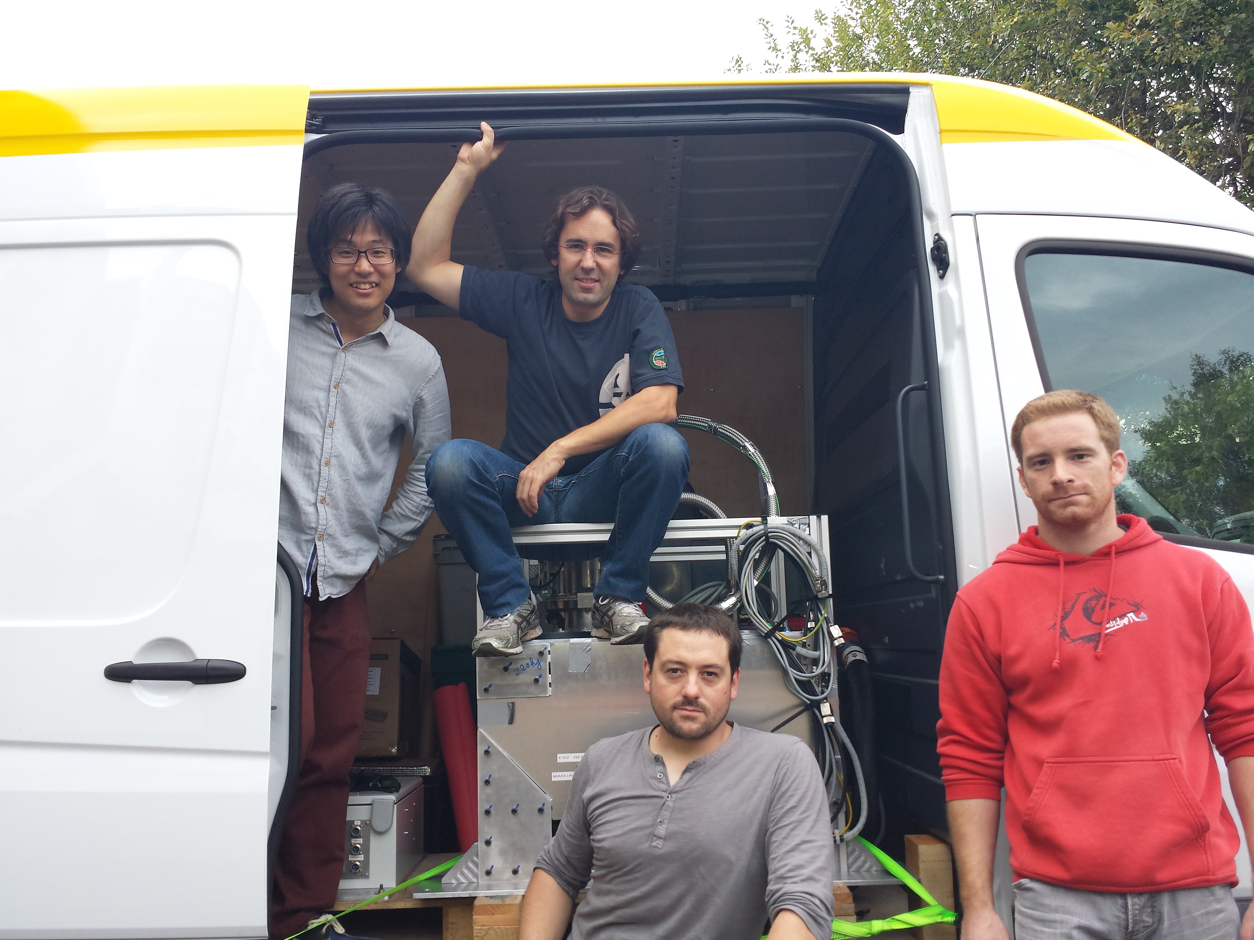
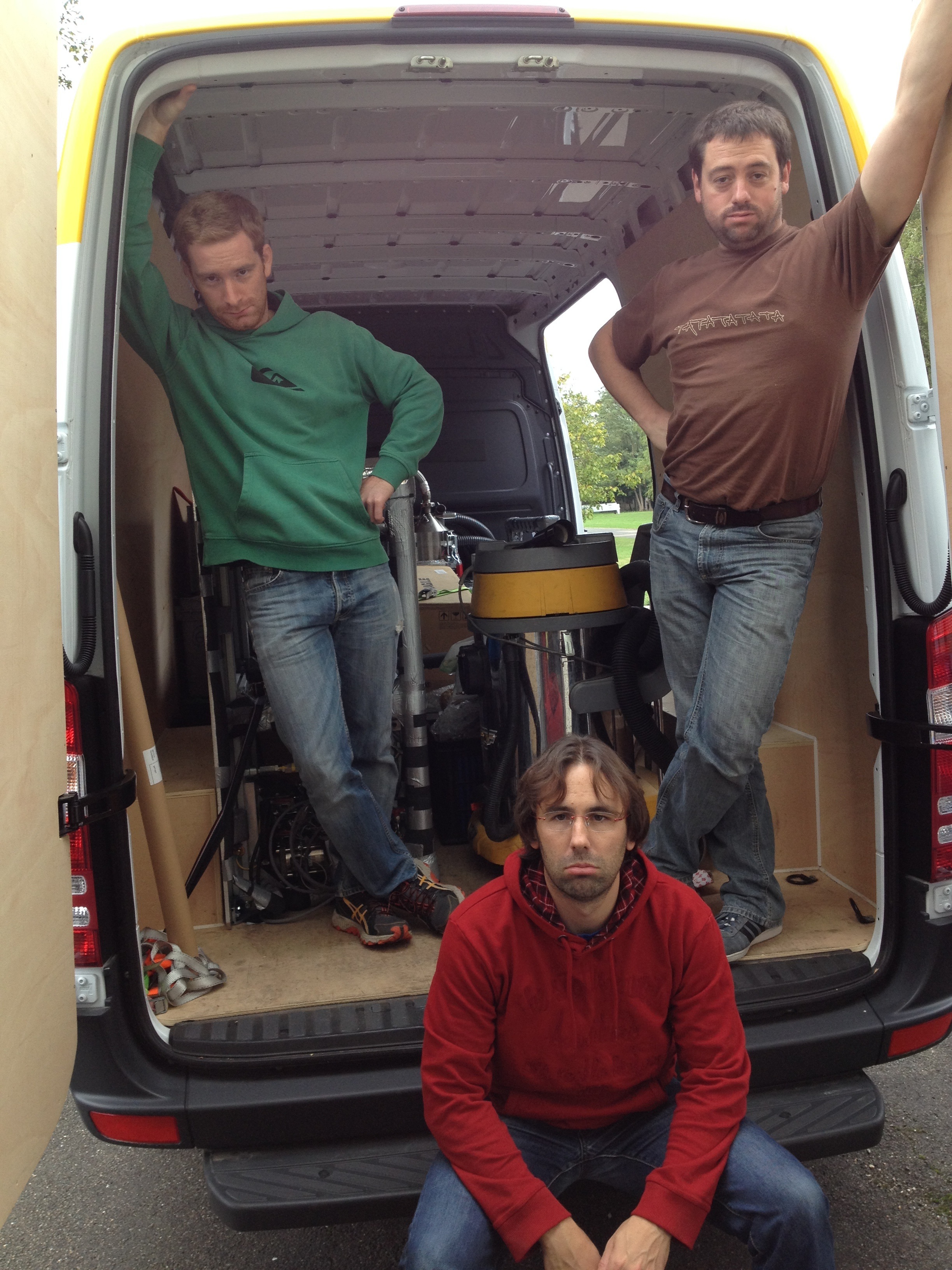
Leaving the plane, Jean-Marie and the rig are waiting in the line for the van.
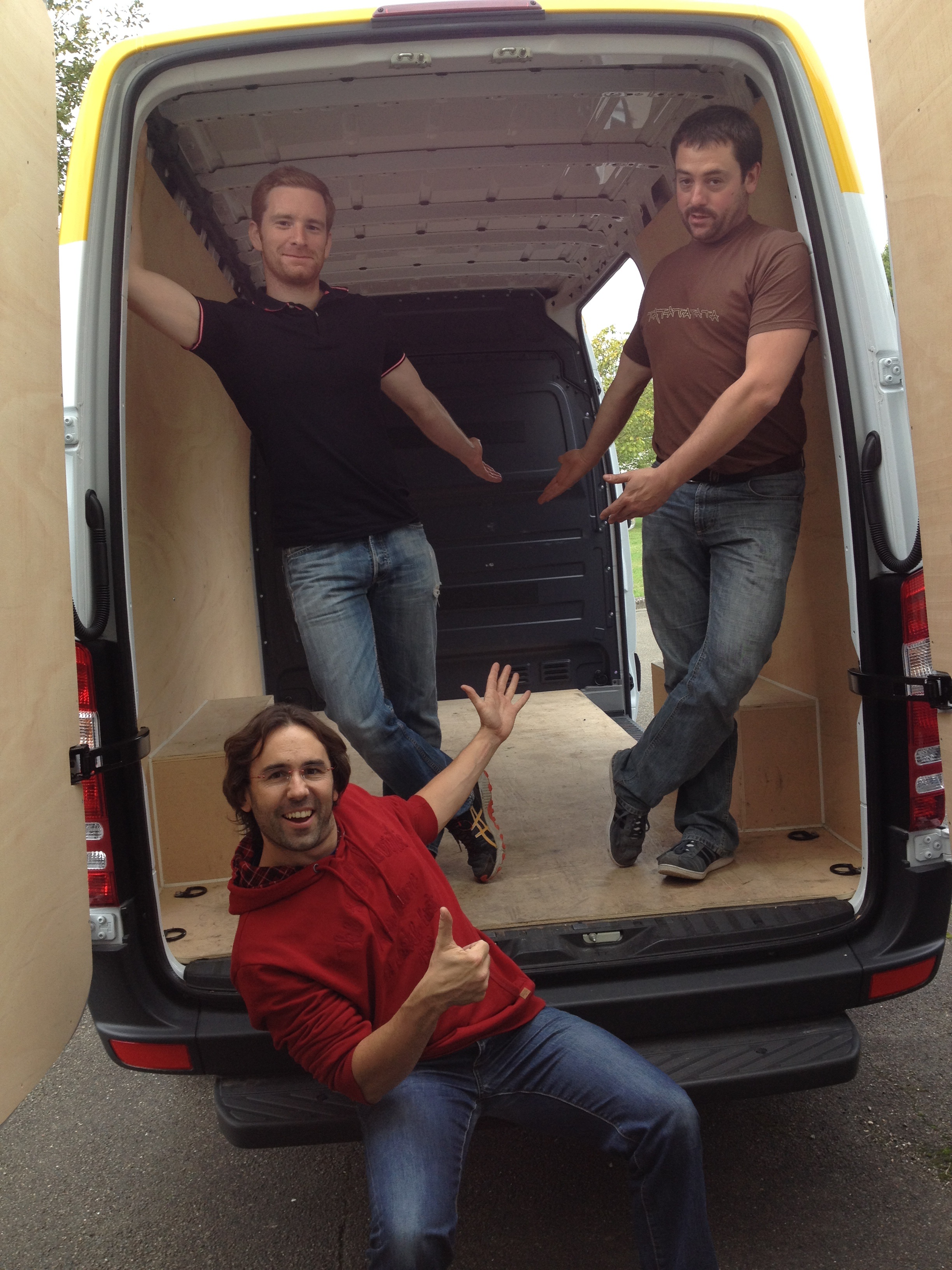
Exhausted but at home! Yet, we still have to unload the rig...
Determined, we did it!
Step 12 2015 ???
"I want more flights !!!" (Koki Kizawa, onboard the plane during the ultimate flight of VP 112 campaign)