The investigation of the chemical mechanisms involved in combustion requires, among other things, the analysis of the flame structure.
The following sections describe the experimental approach implemented at the Institut ∂'Alembert. The video realized by Renaud Jalain, engineer and PhD student, provides an illustration (~6 min):
https://youtu.be/caA61vTcp70
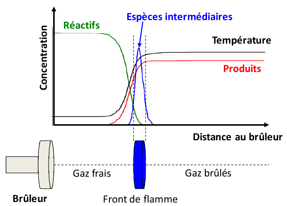
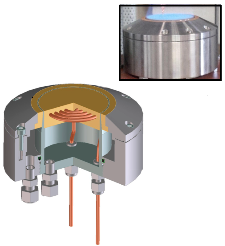
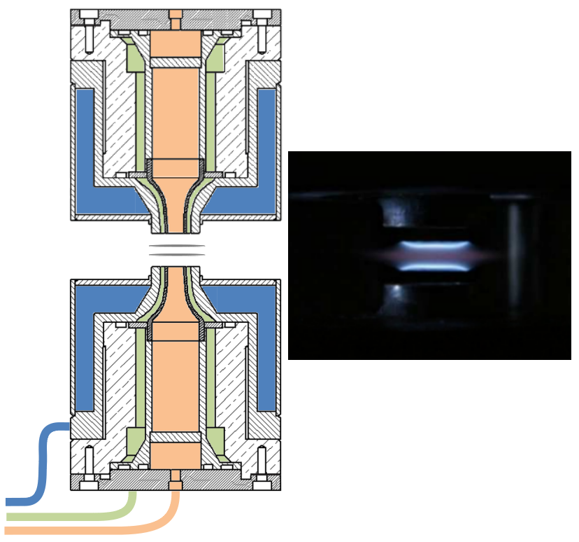
We are interested in premixed flames, where the fuel and oxidant are mixed before the reaction takes place. The typical structural scheme of a premixed flame is given in Figure 1. The heat and radicals produced in the reaction zone diffuse towards the upstream gas layer. The increase in temperature and the presence of the radicals ignites this layer which then becomes a source of heat and radicals which can initiate a further reaction in the next layer, and so on. In the laboratory, this type of analysis is carried out by stabilizing flames on a flat flame burner (figure 2 a) ) or by means of counterflow burners (figure \ref{fig_bruleurs} b) ). The major advantage of these flames is that their composition along the central axis of the burner varies, in theory, only in one direction which is perpendicular to its surface. The analysis of the flame structure then consists of studying the evolution of the concentrations of the chemical species and the temperature as a function of the distance from the burner.
Experimental setup
Burner
The burner used at the institute is a McKenna® burner. This burner is designed by the company Holthuis & Associates and its configuration is a widely used reference in the scientific combustion community. Experiments conducted in different laboratories can be compared on this common basis. These burners are designed so that the mixture at the burner outlet is distributed uniformly over the entire surface and the flow is laminar, stable, and one-dimensional. The burner is shown in Figure 2 a). A sintered brass plate at the burner outlet ensures that the gas flow is laminar and uniform over the entire burner surface. In the presence of the flame, the burner acts as a heat sink, which reduces the speed of flame propagation and therefore limits flame motion. To avoid excessive heating of the burner surface, a cooling circuit is integrated into the sinter. However, due to heat exchange, the flame is no longer adiabatic. As the kinetics of a chemical reaction are very sensitive to temperature, it is then necessary to take into account the heat losses at the burner. The most commonly used solution is to measure the temperature profile along the flame and to integrate it into the calculation when simulating the species profiles.
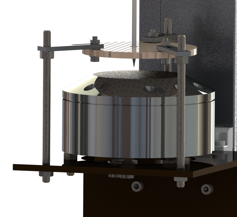
Sampling device
In the present configuration, the concentration of the chemical species present in the flame is measured by means of gas sampling into the flame. This method consists in using a quartz probe to extract a volume of gas from the reactive medium and to direct it to an analysis device. The main advantage of this sampling system is that it allows a large number of species to be analyzed simultaneously. However, it is known that the probe can disturb the medium being probed (flow disturbance, local cooling of the flame). These disturbances depend on the type of probe and the geometry was therefore defined accordingly. The probe used in our measurements has an opening angle of approximately 20˚ and an opening section of 60 μm. These characteristics reduce the disturbances to a minimum.
Analysis device
The gaseous samples are then analyzed using a gas chromatography apparatus (Varian 4000®). The principle of this type of instrument is to separate the different chemical species present in the sample by passing them through a chromatography column (Rt-Alumina BOND MAPD 50m×0.53mm×10.0∕mum, in our case), and to measure them, in turn, by means of one or several complementary detectors (Flame Ionisation Detector (or FID), in our case).
Exemple of results
The successive steps leading to the analysis of the flame structure are summarized in the following animation:
The results presented here illustrate a set of measurements conducted with a CH4/air flame at atmospheric pressure of Φ = 1,67. These measurements are compared with the results of a simulation performed using the open-source code Cantera with the kinetic mechanism developed by Gong et al.

FIGURE 4: Example of comparison of experimental measurements/simulation for a CH4/air flame Φ = 1,67 stabilized at atmospheric pressure
Related Publications
R. Jalain, J. Bonnety, G. Legros and A. Matynia. Doping rich ethylene premixed flames: Influence of C3-C5 alcohols on the structure of the steady one-dimensional laminar flame. Fuel, 307:121793, 2022.
R. Jalain, J. Bonnety, G. Legros, P. Jacobs and A. Matynia. Study of a gasoline surrogate blended with pentanol isomers: sooting propensity and flame structure analysis. Proceedings of the European Combustion Meeting, 7p., 2019.
L. Pillier, M. Idir, J. Molet, A. Matynia, and S. de Persis. Experimental study and modelling of NOx formation in high pressure counter-flow premixed CH4/air flames. Fuel, 150:394–407, 2015.
A. Matynia, J. Molet, C. Roche, M. Idir, S. de Persis, and L. Pillier. Measurement of OH concentration profiles by laser diagnostics and modeling in high-pressure counterflow premixed methane/air and biogas/air flames. Combustion and Flame, 159(11):3300–3311, 2012.
A. Matynia, M. Idir, J. Molet, C. Roche, S. de Persis, and L. Pillier. Absolute OH concentration profiles measurements in high pressure counterflow flames by coupling LIF, PLIF, and absorption techniques. Applied Physics B, 108(2):393–405, August 2012.
A. Matynia, J.-L. Delfau, L. Pillier, and C. Vovelle. Comparative study of the influence of CO2 and H2O on the chemical structure of lean and rich methane-air flames at atmospheric pressure. Combustion, Explosion, and Shock Waves, 45(6):635–645, 2009.